Jump to a question in this guide
- What is the box with four ducts actually doing?
- How does it recover heat without sending the same air back?
- What changes when the label says ERV?
- What do the fans, filters and core each contribute?
- Does it have its own ducts, or share the furnace ducts?
- How does outdoor air reach a closed bedroom?
- What does a balancing test establish?
- Which control is actually telling it to run?
- Why does winter change the sound or airflow?
- Is water below the cabinet normal condensation?
- How do I choose the right maintenance instructions?
- What can I do before the service appointment?
- What do noise, weak air and warning messages tell me?
- What if the air still feels stale or the windows stay wet?
- What should useful service actually include?
- What matters when replacing equipment or handing over the home?
Five things to know
- Follow both complete air journeys: outdoor intake to rooms, and room collection to outdoor exhaust.
- The core recovers heat; an ERV also transfers some moisture. Neither guarantees a room condition or replaces local source control.
- Dedicated and integrated duct arrangements have different distribution and central-blower requirements.
- Unit balance, room delivery and completed equipment care are different service questions.
- Match the unit, installed core, filters and controls to the applicable manual before any care or change.
What is the box with four ducts actually doing?
An air exchanger can be running downstairs while a bedroom still feels stuffy. Understanding that mismatch starts with its actual job: replacing some indoor air with outdoor air and distributing that air where people live. A heat recovery ventilator, or HRV, recovers heat during that exchange. An energy recovery ventilator, or ERV, also transfers some moisture.
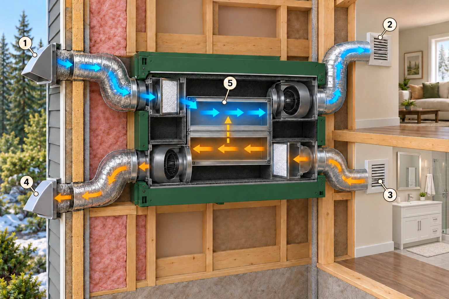
Follow the two complete air journeys
Outdoor intake, supply to rooms, indoor collection and outdoor exhaust. Two separate air journeys pass through a deliberately simplified recovery-core section; the dashed gold arrow shows winter heat transfer from warm outgoing air toward cooler incoming air. The room scenes and port positions are conceptual, not a distribution or installation plan.
1. Outdoor intake
Brings outdoor air to the ventilator through its identified hood and duct.
2. Supply to rooms
Carries the incoming stream toward the occupied spaces.
3. Indoor collection
Collects house air for the outgoing route.
4. Outdoor exhaust
Discharges the departing stream to outdoors.
5. Cabinet and core
Contain the intended passages and recovery process; exact internal routing varies by model.
Picture two complete journeys. Outdoor air travels through an intake hood, a duct and the ventilator before reaching the house. Indoor air travels from collection grilles back through the ventilator and leaves through an exhaust hood. The four connections on the cabinet are the indoor and outdoor ends of those two journeys. Their positions vary between models.
The labels matter more than which collar is on the left. “From outdoors” and “to the house” belong to the incoming route. “From the house” and “to outdoors” belong to the outgoing route. In normal exchange, both routes operate together. Internal passages, filters, fans and the recovery core each have a different job along them.
This is ventilation equipment, not a replacement for the furnace, air conditioner or local pollution control. A closed cabinet and a running sound cannot establish how much outdoor air reaches each room. The useful first question is: which ducts serve this home, and where does each route actually begin and end? Trace visible labels without disconnecting anything.
Sources for this chapter
How does it recover heat without sending the same air back?
Inside a typical plate-core ventilator, outgoing and incoming air travel through neighbouring passages separated by thin material. During cold weather, the warmer house-air side gives up heat through those surfaces to the colder incoming side. The incoming air is tempered before distribution; the departing air becomes colder as it moves toward the exhaust.
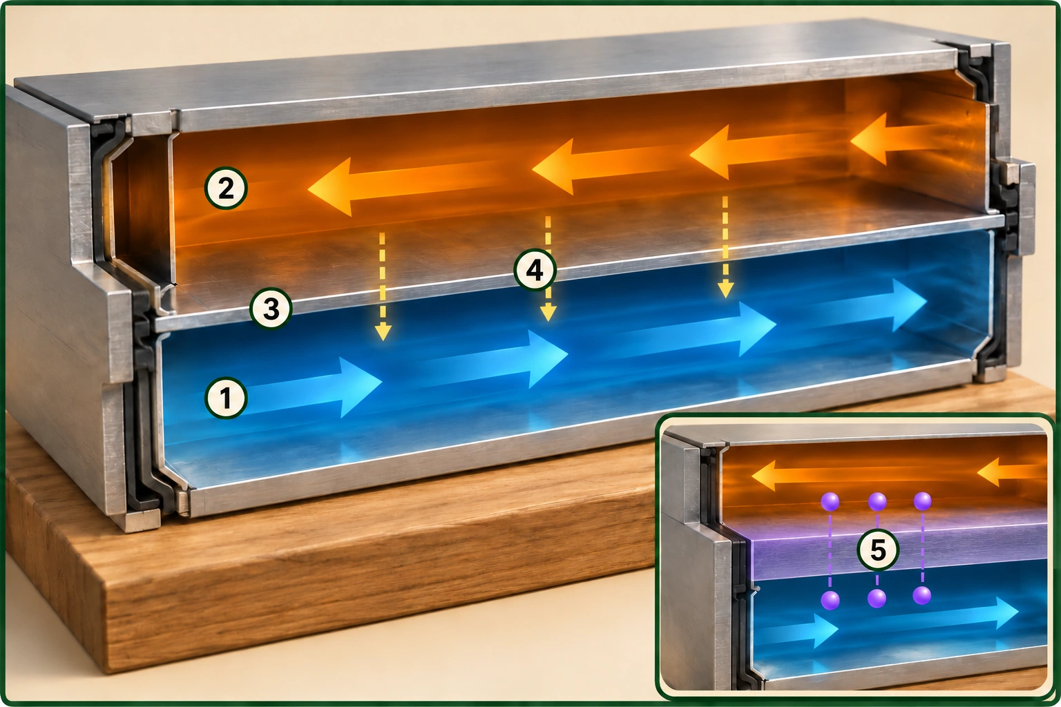
A close look at the recovery surface
Incoming passage, outgoing passage and separating surface. Lengthwise arrows show air; dashed gold arrows show winter heat moving across intact metal from the warmer upper passage to the cooler lower one. The ERV inset adds moisture-transfer links; their direction depends on conditions.
1. Incoming passage
Carries outdoor air toward the home.
2. Outgoing passage
Carries house air toward discharge.
3. Separating surface
Provides the intended heat-transfer surface between passages.
4. Heat transfer
Moves energy between warmer and cooler sides without an intended open air shortcut.
5. ERV moisture transfer
Shows the additional conceptual moisture exchange; direction follows conditions and is not a humidity guarantee.
The intended transfer is heat across the core, not a shortcut that simply mixes the two air streams. The illustration shows that intended mechanism. It does not demonstrate the leakage, sealing or condition of a real unit. Port labels, internal design and the manufacturer's airflow diagram determine the actual route through a particular cabinet.
Recovery also does not mean the incoming air must feel as warm as a heating register. Outdoor conditions, the core, airflow and the distribution arrangement affect its temperature. A cool-feeling supply grille alone does not prove failure. Persistent discomfort needs a look at delivery, operating mode and the equipment's condition, rather than an assumption that recovery makes room-temperature air.
In an air-conditioned home, the direction of useful heat transfer can reverse when outdoor air is warmer than indoor air. The cooler exhaust stream can take some heat from the incoming stream. There is still a heating or cooling job left for the home's other equipment. No percentage saving or delivered-air temperature is promised by this conceptual explanation.
Sources for this chapter
What changes when the label says ERV?
An ERV core also permits moisture transfer between its air streams. In a cold, dry winter, that can retain some moisture that would otherwise leave with the exhausted house air. During warm, humid conditions with a drier air-conditioned interior, some incoming moisture can pass toward the outgoing stream instead. The direction depends on the conditions on both sides.
That makes an ERV different from a device that simply adds water to the home. It is also different from a dehumidifier that collects water while treating room air. Recovery moderates part of the moisture exchange. It does not guarantee a particular indoor humidity, eliminate every condensation problem or remove the moisture from an active plumbing leak.
In winter, exchanging moist indoor air for outdoor air that contains less water vapour can lower indoor humidity. This is dilution through air exchange, not heat acting as a water-removal device. But a home with substantial moisture production can still have wet windows, while another home may already be too dry. Cooking, bathing, occupancy, leaks, outdoor conditions and the building's cold surfaces all belong in that explanation.
Choosing HRV versus ERV therefore needs more than a province name or a wet-window photograph. Ask how the proposed equipment fits the climate, the home's moisture sources and existing heating or cooling. Confirm the exact core and replacement compatibility. Similar-looking cores are not permission to exchange them or use the same cleaning method.
Heat recovery, moisture recovery and moisture removal do different jobs
- HRV coreTransfers heat between intended air streams. Winter exchange may dry indoor air; it is not a dehumidifier with a room-humidity guarantee.
- ERV coreTransfers heat and some moisture between the streams. Transfer direction follows conditions; it does not guarantee a humidity target.
- Moisture-source repairStops or reduces the identified source, such as a water leak. Recovery ventilation does not repair the source.
Conceptual distinctions; equipment choice and controls require the actual home, climate and model. No numeric humidity target or universal operating setting.
Sources for this chapter
What do the fans, filters and core each contribute?
The fans create the pressure differences that move air along the ducts. The core transfers heat, and in an ERV some moisture, between the intended streams. Filters intercept material before it loads the equipment. Those jobs depend on one another: an efficient core cannot recover usefully from a route that is not moving its intended air.
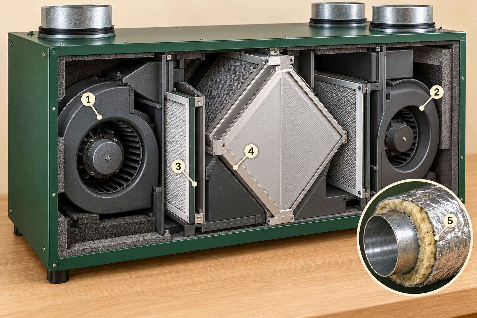
See the filters, core and two fans in context
Two fan assemblies, fitted filter panels and the recovery core. The inset separates the inner air duct, insulation and outer jacket. This component cutaway identifies the parts; complete model-specific airflow routes and safe access are separate questions.
1. Fan assembly on one air route
One of the two assemblies that move air; the exact route assignment requires the matching model airflow drawing.
2. Fan assembly on the other air route
The second air-moving assembly; partial collars alone do not identify supply versus exhaust.
3. Fitted filters
Intercept material before it loads the protected equipment; type and care vary.
4. Recovery core
Transfers heat and, for an ERV, some moisture.
5. Insulated duct and outer jacket
Limit unwanted heat exchange and condensation along the cold route.
Filters usually need attention on both the incoming and outgoing paths. Outdoor debris is only part of the load; indoor dust also travels toward the core. The fitted filter's size, material and position matter. A different filter that happens to fit in the opening may create a different restriction, and some optional filters are disposable rather than washable.
The cabinet and its seals help keep the intended passages working. Dampers, where fitted, can change a route during modes such as recirculation or defrost. Insulated outdoor ducts limit unwanted heat exchange and condensation along cold runs. These are recognizable parts of one system, not a shopping list of interchangeable upgrades.
Use the cutaway to learn their positions and purposes, not to open your own unit while it runs. Internal work involves electrical power, moving parts and thin metal. The correct manual and service provider should establish who can perform each task, how the equipment is made safe and which replacement parts actually belong to that model.
Sources for this chapter
Does it have its own ducts, or share the furnace ducts?
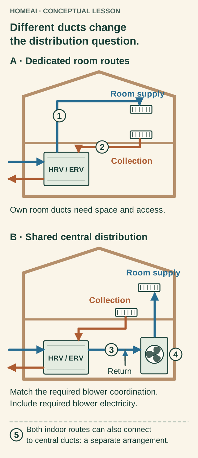
In a fully dedicated arrangement, the ventilator has ducts supplying living spaces and ducts collecting air from selected rooms. It can serve a home heated by radiators, baseboards or another system without a central distribution fan. Dedicated means the ventilation has its own distribution routes; it does not mean every room receives the same amount of air.
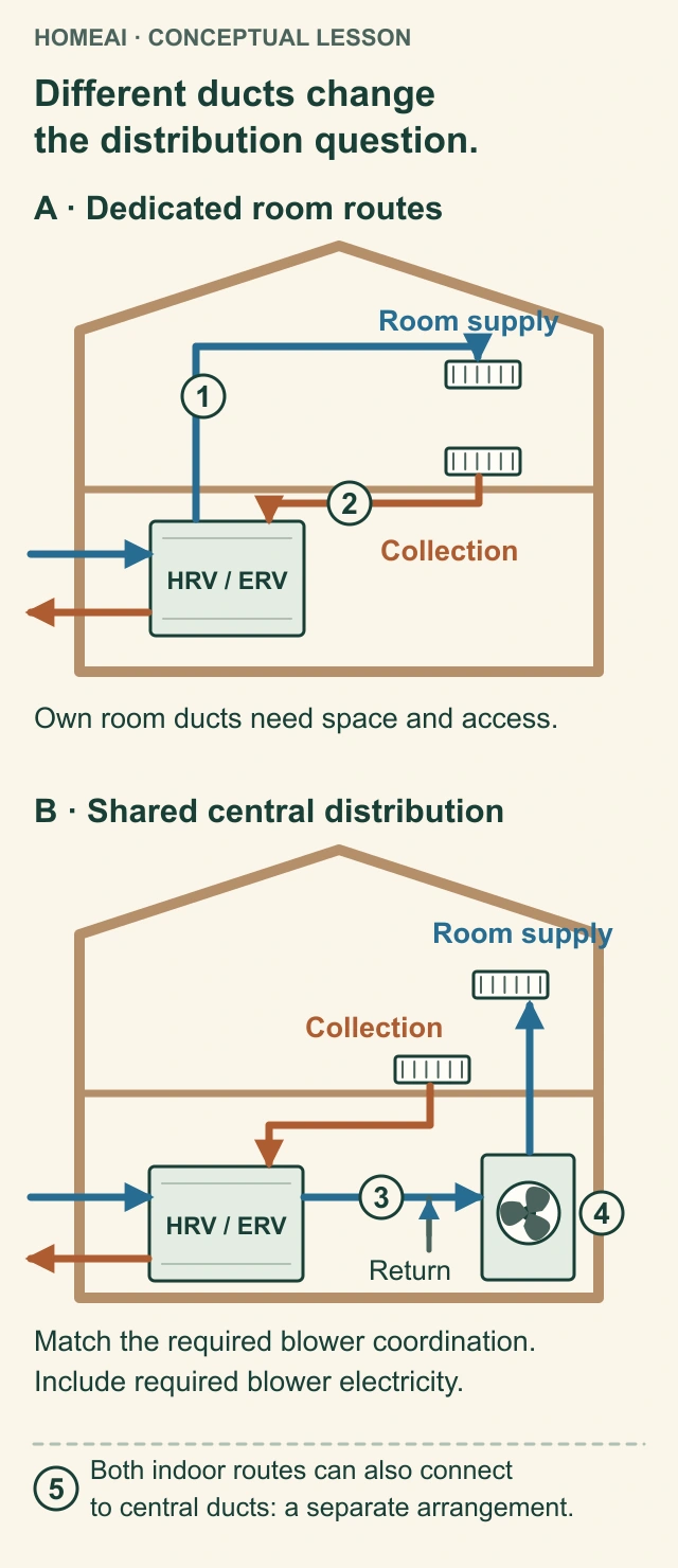
Different ducts change the distribution question
Dedicated ducts have their own room routes. Shared distribution uses central ducts and needs the blower relationship checked for the exact model and configuration. These conceptual sections prescribe no connection positions or duct dimensions. The short grey return stub identifies a separate connection; its room route is not traced.
Dedicated supply
The blue route has its own duct to the occupied space. Additional room routes need space and access.
Dedicated collection
The orange route collects house air separately for the ventilator. Its outdoor route is separate from the incoming route.
Central return connection
The shared-distribution concept introduces incoming ventilation air into the central return route. This is not a prescribed physical connection location. The grey return stub is separate from the orange collection grille; no central-return room route is drawn.
Central blower
Where the actual arrangement requires the blower, ventilation depends on that coordination and its electricity use. The named manuals differ on particular configurations.
Another integrated arrangement
Connecting both indoor ventilator routes to central ductwork is a separate configuration. Identify the actual routes and matching instructions rather than copying either concept.
Read all the diagram text
- HOMEAI · CONCEPTUAL LESSON
- Different ducts change the distribution question.
- A · Dedicated room routes
- Room supply
- Collection
- Own room ducts need space and access.
- B · Shared central distribution
- HRV / ERV
- Match the required blower coordination.
- Include required blower electricity.
- Both indoor routes can also connect to central ducts: a separate arrangement.
- 1
- 2
- 3
- 4
- 5
- Return
- Different ducts change the distribution question
- Different ducts change
- the distribution question.
- Both indoor routes can also connect
- to central ducts: a separate arrangement.
Other installations introduce ventilation air into the return side of a forced-air system, whose blower and ducts help distribute it. Some retain dedicated collection ducts from bathrooms or other rooms. A simplified arrangement may connect both indoor ventilator routes to central ductwork. These are different arrangements, even when the ventilator cabinets look identical.
The required relationship with the central blower depends on the exact arrangement and manufacturer. For example, the current Fantech HERO manual requires blower operation for its illustrated integrated arrangements; the Venmar manual distinguishes several configurations and their synchronization requirements. That is why a blanket instruction to set every furnace fan permanently on, or permanently off, would be wrong.
Separate ducts can place supply and collection where ventilation needs them without depending on heating circulation for that route. The tradeoff is room and access for those additional ducts. Shared distribution can use existing central routes, but it ties ventilation delivery to that system’s airflow and controls. If the central blower must run for ventilation, its electricity use belongs in the operating-cost discussion too.
Ask the installer to identify the arrangement in your home and explain when each fan must operate. The answer should match the model manual and commissioning record. Do not move duct connections, change installer configuration menus or disconnect a control to experiment. Shared-building systems need the building operator involved before any change affecting other homes.
Identify the installed routes before choosing a fan instruction
- Fully dedicatedVentilation supplies and collects through its own ducts. Central heating ducts are not its required room-distribution route in this concept. Separate room routes need space and access for additional ducts.
- Partially dedicated / exhaust ductedDedicated collection with supply introduced into central distribution. Central-blower requirements depend on the model and approved configuration. Shared distribution uses central routes; required blower operation and electricity belong in the assessment.
- Simplified integratedBoth indoor ventilator routes connect to central ductwork in the illustrated manufacturer arrangements. Correct configuration and central-blower relationship matter; no DIY connection recipe.
These describe concepts in the named manuals; actual topology, terminology and local requirements vary.
Sources for this comparison
Further reading: Natural Resources Canada · Keeping the Heat In, section 9.4: ventilation and combustion air; Venmar Ventilation ULC / Broan-NuTone Canada · AI-series User and Installer Manual,1107074WEB revF; Fantech / Systemair · HERO Series Installation, Operation and Maintenance Instructions,428486-004.
Sources for this chapter
How does outdoor air reach a closed bedroom?
Supplying air to the house and supplying air to an occupied room are related but different questions. In a dedicated system, a bedroom grille may be part of the ventilation supply. In an integrated system, a heating supply can carry a mixture of recirculated house air and ventilation air. A familiar grille shape alone does not identify its role.
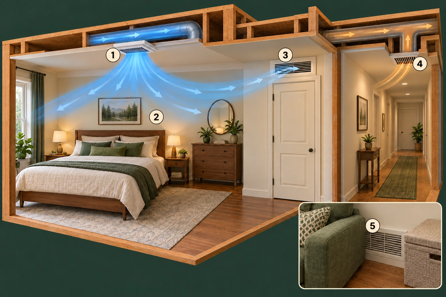
Air needs a route through the room
Room supply, intended transfer opening and hallway collection. Air must have a route through the occupied space as well as a running ventilator. The opening shown is conceptual, not a required grille, door cut, fire-rated modification or measured delivery result.
1. Room supply
Introduces the air delivered by the identified distribution arrangement.
2. Occupied space
The area whose normal use and complaint need consideration.
3. Transfer route
Allows air to move beyond the room; exact design and restrictions need assessment.
4. Collection path
Carries air toward the outgoing ventilation route.
5. Covered-grille inset
Shows a recognizable obstruction to report, without diagnosing the whole system.
Air also needs a route through and out of the room. A closed door, a tight gap above carpet or a blocked transfer opening can affect exchange with the rest of the house. The room picture shows the complete intended path, including that transfer route. It is a concept, not a prescription for cutting a particular gap into a door.
Keep furniture and stored items from covering identified grilles. Note whether the complaint occurs with the door open or closed, overnight or throughout the day, and whether the central fan is running. Those observations help a technician choose a useful test. They do not establish the required airflow or justify adjusting a balancing damper yourself.
If a room is cold as well as stuffy, separate the heat-delivery question from ventilation. A heating-airflow assessment may need different measurements from an outdoor-air delivery assessment. Ask which one the proposed visit will investigate. A whole-unit balance result by itself does not answer whether this room receives the intended air under its normal door conditions.
Sources for this chapter
What does a balancing test establish?
Balancing compares the ventilator's supply and exhaust airflows in a defined operating condition. Duct resistance, dirty filters, a blocked hood, fan trouble or damper problems can affect the two routes differently. The objective is the system's specified balance, not a homeowner guessing that two grilles feel equally breezy.
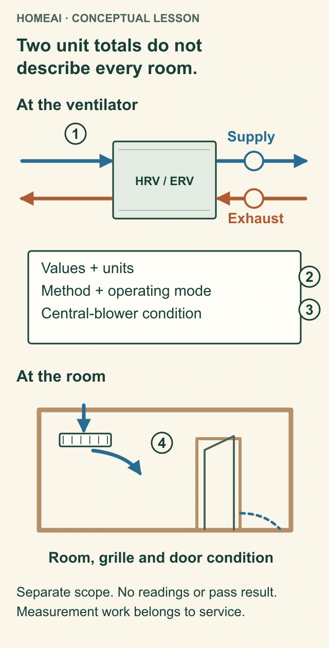
Two unit totals do not describe every room
Unit balance compares measured supply and exhaust under stated operating conditions. The room view asks a different distribution question. No measured values or pass result are shown.
Unit totals
Supply and exhaust are two different airflows. A recorded fan setting is not itself a measured airflow.
Interpretable readings
Ask for the values with units and the measurement approach. This picture supplies no instrument setup or owner balancing test.
Operating conditions
Mode and the relevant central-blower condition identify what the measurements represent. One condition does not establish every operating mode.
Room delivery
Room, grille and door/distribution conditions need their own relevant investigation. Unit totals alone do not show how much reaches a particular room.
Read all the diagram text
- HOMEAI · CONCEPTUAL LESSON
- Two unit totals do not describe every room.
- At the ventilator
- HRV / ERV
- Supply
- Exhaust
- Values + units
- Method + operating mode
- Central-blower condition
- At the room
- Room, grille and door condition
- Separate scope. No readings or pass result.
- Measurement work belongs to service.
- 1
- 2
- 3
- 4
- Two unit totals do not describe every room
- Two unit totals do not
- describe every room.
When exhaust removes more air than the supply replaces, the ventilator can contribute to lower pressure in the home. That can interact with other exhaust devices and draw combustion products from susceptible fuel-burning equipment. Excess supply can push moist indoor air through leaks toward cold wall or roof spaces, where it can cool and condense. These are reasons to assess the complete installation, not diagnoses from a door movement or a draft.
Airflow is a volume per unit time, commonly reported in litres per second or cubic feet per minute. Fan speed is not the same quantity. A percentage on a control or a large number in a sales description does not establish installed flow. The method, measurement locations and operating condition belong beside the recorded result.
Some equipment assists with airflow verification or automatic balancing; other equipment uses model-specific pressure references and measurements. Those features still depend on correct installation and configuration. They do not turn a display into a certificate that every room is ventilated, the ductwork is intact or all other exhaust appliances are harmless to house pressure.
Ask for the intended values, measured supply and exhaust, units, selected mode and central-blower condition. If room delivery is the concern, ask for the relevant room measurements too. Keep the report with the equipment identity and date. Changes to ducts, controls or equipment may warrant reassessment; cleaning alone and balancing are different scopes of work.
Sources for this chapter
Which control is actually telling it to run?
A home can have a main wall control, a bathroom boost timer, an onboard switch and a connection to the heating system. Depending on the equipment, one signal may override another. A timer still calling for ventilation can explain why the cabinet is running differently from what the main control appears to request.
The words on the control need their own explanation. Exchange brings outdoor air in and sends indoor air out. Recirculation, where available, moves indoor air without providing that same outdoor exchange. Standby, intermittent and automatic modes mean what that model's instructions say. Recirculation is not available in every unit or duct arrangement.
A humidity control is another example of why guessing from a dial is unreliable. A dehumidistat can request ventilation when measured humidity exceeds its threshold; raising that threshold is not necessarily a request for more ventilation. Summer outdoor moisture conditions can also change the usefulness of a humidity-based request. No single dial setting suits every home or season.
Have the installed control demonstrated using its own instructions: normal exchange, temporary boost, automatic operation and the meaning of reminders or warnings. Record the selected mode and any active timer before reporting a problem. Leave commissioning values and installer menus to the service provider rather than resetting them to see whether a symptom disappears.
Sources for this chapter
Why does winter change the sound or airflow?
As warm, moist exhaust air cools through a recovery core, water can condense on cold surfaces. In sufficiently cold conditions it can form frost. Accumulation can restrict the passages. Cold-climate equipment therefore needs a way to manage frost, but the method and timing depend on the unit and its operating conditions.
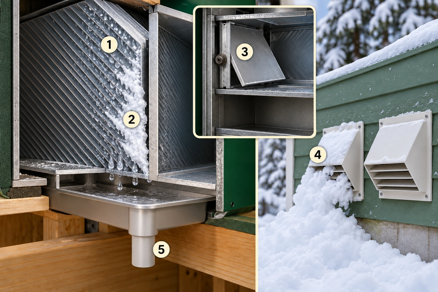
See where frost, water and outdoor obstruction differ
Cooling core surface, frost, a damper and an outdoor opening. These are different winter questions: frost control inside the equipment and snow obstruction outside. The tray and short drain stub identify an HRV collection example; the full installed drain and active defrost route are not drawn.
1. Cooling exhaust surface
Explains where water can condense as heat leaves the outgoing stream.
2. Frost accumulation
Shows a possible restriction, not a diagnosis of the illustrated home.
3. Damper component example
Some winter strategies change fan or damper operation; this close-up does not draw a complete active defrost route or prescribe its position.
4. Outdoor opening
A separate part of the airflow route where snow/debris can obstruct flow.
5. HRV collection tray and short drain stub
Identify condensate collection and the start of its drain route; the downstream destination is not drawn.
Some designs temporarily change fan or damper operation; others use different frost-control arrangements. A recirculation defrost cycle, where provided, redirects warm indoor air through the equipment for part of the cycle. A change in sound or outdoor supply during that period can be intentional. It is not evidence that every interruption is normal.
Record the outdoor weather, displayed mode, duration and whether normal operation resumes. Persistent loss of exchange, recurring warnings, unusual vibration or visible water damage needs service. Do not defeat a damper, alter a frost setting, add a heater or open an operating cabinet to watch the mechanism. The manual's installer diagnostics are not a household observation checklist.
The winter picture also shows the outdoor openings. Snow, leaves or ice can obstruct a route before air reaches the core. Identify the actual intake and exhaust from safe ground-level observations and the installed documentation. Keep a safe distance from icy surfaces; ask for service where access or removal would require climbing, dismantling or working near electrical equipment.
Sources for this chapter
Is water below the cabinet normal condensation?
Condensation produced inside an HRV needs its designed collection and drainage path. Where the model has a drain, the pan, connection and tubing form part of that path. Their appearance and arrangement vary. The manuals reviewed here specify drains for their HRV examples and distinguish their ERV models; this is not proof that every ERV everywhere is drain-free.
Water on the floor is not an acceptable substitute for drainage. It can come from a drainage problem, condensation on a cold duct, damaged insulation or another nearby source. Record where it first appears and which surfaces are wet without opening the equipment. A stain shows a location or history to investigate, not the cause or current severity by itself.
Insulation and its outer jacket matter because a cold duct can meet warm, humid surrounding air. A torn jacket, wet insulation or crushed run deserves attention. The water may be outside the air passage rather than coming from the core. Photograph visible damage and include its position in the service request instead of treating every drip as a blocked drain.
Do not pour water into the cabinet, probe a drain, detach tubing or copy a generic trap-cleaning recipe. Model instructions, safe access and the actual drainage arrangement control that work. If water is approaching electrical equipment, avoid the area and obtain urgent appropriate help rather than touching the unit, cord or wet surfaces.
Sources for this chapter
How do I choose the right maintenance instructions?
Start with the manufacturer's name, complete model and product label, then the matching manual revision and installed core. A family name such as “air exchanger” is not enough. Obtain the matching control instructions as well. If the identification is inaccessible, ask the service provider to record it during safe service rather than removing covers to find it.
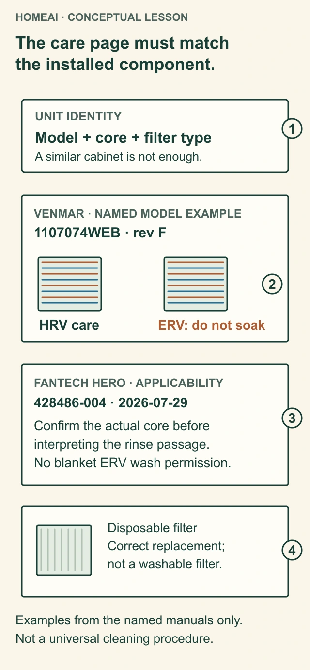
The care page must match the installed component
Unit identity, installed core and filter type select the care instructions. The two named manuals illustrate why a general rinse passage is not permission to wash every recovery core.
Unit identity
Match the complete model, installed core and filter option to the applicable instructions and edition. Cabinet resemblance does not settle the match.
Venmar rev F example
The named manual separates HRV and ERV core care and explicitly prohibits soaking its energy recovery core in water. This is a model example, not a national rule for all cores.
Fantech applicability
The actual HERO document is 428486-004 dated July29,2026. Confirm the exact core and applicable instructions before interpreting its general rinse passage; no universal ERV washing permission follows.
Disposable filters
The named manuals identify disposable filter options that need the correct replacement rather than washing. Do not transfer instructions from another filter type.
Read all the diagram text
- HOMEAI · CONCEPTUAL LESSON
- The care page must match the installed component.
- UNIT IDENTITY
- Model + core + filter type
- A similar cabinet is not enough.
- VENMAR · NAMED MODEL EXAMPLE
- 1107074WEB · rev F
- HRV care
- ERV: do not soak
- FANTECH HERO · APPLICABILITY
- 428486-004 · 2026-07-29
- Confirm the actual core before interpreting the rinse passage.
- No blanket ERV wash permission.
- Disposable filter
- Correct replacement; not a washable filter.
- Examples from the named manuals only.
- Not a universal cleaning procedure.
- 1
- 2
- 3
- 4
- The care page must match the installed component
- The care page must match
- the installed component.
- Confirm the actual core before
- interpreting the rinse passage.
- Correct replacement;
- not a washable filter.
The current Venmar manual reviewed for this guide has separate HRV and ERV core-care instructions, including a specific prohibition on soaking its ERV core. Its standard and optional filters also have different care requirements. That example shows why a video about another cabinet is not sufficient instruction for yours.
The current Fantech HERO manual contains core-rinsing instructions and separate disposable-filter limits, while placing its procedures within an approved-personnel scope. Its illustrated core-care passage does not clearly resolve every HRV-versus-ERV variant on its own. Where applicability is unclear, confirm the exact core with Fantech; do not turn that passage into permission to wash every ERV core.
The manual comparison picture is a decision aid: match unit, core, filter and applicable page before deciding who should do the task. It deliberately supplies no generic washing solution, drying time or calendar for every product. A correct fit and an apparently clean component do not establish that its material can tolerate the same treatment as another one.
Sources for this chapter
What can I do before the service appointment?
Useful owner preparation begins outside the cabinet. Keep the model information and manual available, note the control state, and identify the rooms affected. From safe accessible locations, look for covered grilles, visible hood obstruction, damaged duct jackets or new water staining. A clear description often helps more than a series of guessed adjustments.
Routine care is not the same scope on every unit. Follow the identified manufacturer's allocation of work and have the provider demonstrate any owner task that the model permits. If the instructions require approved personnel, access is awkward or the procedure is unclear, arrange service. This guide does not supply an alternative internal-cleaning method.
A maintenance reminder is a prompt to check the applicable task, not proof that a filter is dirty or that the core is sound. Conversely, a system can have a real restriction before a reminder appears. Record what was actually inspected or replaced, the correct part and the date; clear reminders only as the appropriate instructions provide after the work.
Do not run the ventilator without its intended filters or operate it open for comparison. Avoid resetting a tripped breaker or repeatedly restarting equipment to clear a recurring fault. Electrical damage, burning smells or water near powered equipment require an appropriate urgent response. Internal repairs and testing belong with someone equipped and permitted to perform them safely.
Sources for this chapter
What do noise, weak air and warning messages tell me?
A new rattle, scrape or strong vibration is different from the familiar change between normal and boost operation. Note where it is loudest, whether it follows a timer request, and whether the sound reaches a particular room through a duct. Record a short observation from a safe position; the recording supports a complaint without diagnosing a motor.
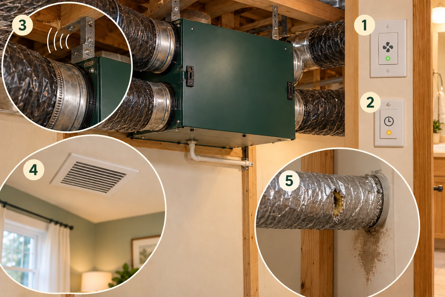
Describe what changed without opening the cabinet
Control state, boost request, sound location, affected grille and duct-jacket damage. Describe the actual installed control and any message, the location and timing of the change. These pictured observations help define service without identifying a failed part or the cause of a stain.
1. Control identity and message
Report the exact installed control and displayed information, without entering installer menus.
2. Boost request
Note whether an auxiliary control is calling for a different operating mode.
3. Noise location
Describe where a changed sound is heard rather than naming an untested failed part.
4. Affected room grille
Record whether the issue concerns one room or wider distribution.
5. Duct-jacket tear and nearby discolouration
Record the visible jacket damage, nearby discolouration and any change. Appearance alone does not establish their cause or present severity.
Weak air can originate at an outdoor opening, filter, core, fan, duct or room route. The symptom does not identify which one. Describe whether the change affects the whole home or one room, whether it began after work or severe weather, and whether a warning appeared. Do not alter several controls and grilles before the technician sees the original condition.
An error or warning is model-specific information. Photograph the exact displayed code and control identity without entering hidden menus. The same letters on another brand need not mean the same thing. A service provider may need the full code, operating condition and repeat history rather than the broad statement that the screen says “service.”
Ask whether the proposed visit covers the complaint's likely scope: equipment condition, airflow measurement, control response or room distribution. A cleaned cabinet might address dirt without investigating a transmission path for noise. A motor repair might restore operation without proving the intended room delivery. The job should finish with a clear explanation of what was checked and what remains unresolved.
Sources for this chapter
What if the air still feels stale or the windows stay wet?
Treat the ventilator as one part of the indoor-air system. A room may have a local pollutant source, a moisture source or an incomplete air route even while the unit exchanges air. Check the pattern: one room or several, particular activities, a door normally closed, or a change in household occupancy. That pattern helps define the investigation.
A humidity reading describes conditions at that sensor's location and time. It does not prove whole-house ventilation or explain every wet window. Surface temperature and air movement at the window also matter. A carbon dioxide trend can support an occupancy-and-ventilation discussion, but one room sensor is not an all-pollutant safety certificate or a substitute for the appropriate tests.
Reducing a source is often part of the solution: a water leak needs repair, and cooking pollutants need suitable local capture. Outside air is not always clean either. Smoke or other outdoor pollution requires a specific operating plan using current public advice and the equipment instructions. Neither a basic ventilator filter nor a promise of “fresh air” establishes comprehensive smoke or gas removal.
An HRV or ERV is not the emergency response to a carbon monoxide alarm. Leave the home immediately for fresh air, do not look for the source, and call 9-1-1 or local emergency services from outside. Return only after a professional has fixed the problem. Turning up ventilation and waiting to see whether the alarm stops is not a safe test.
Sources for this chapter
What should useful service actually include?
Request the task you need in plain terms. “Routine care for this model” asks a different question from “verify supply and exhaust balance” or “investigate the closed bedroom.” A good scope identifies the unit, installed arrangement, complaint and agreed measurements. Ask what access, testing and reporting are included before assuming a general furnace visit covers the ventilator.
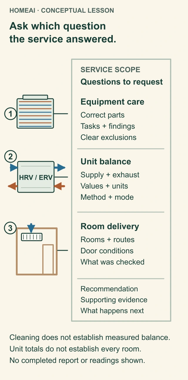
Ask which question the service answered
Equipment care, measured unit balance and room delivery answer different questions. Use the illustrated scopes to ask what was checked and what remains unanswered; this is not a completed property report.
Equipment care
Identify the correct components actually inspected, cleaned or replaced, with findings and exclusions. A care record alone does not establish measured balance.
Measured unit balance
Ask for the measured supply and exhaust values, their units, the measurement method and the operating conditions, including the central blower where relevant.
Room delivery
Identify which rooms and door/distribution conditions were investigated. A unit reading or one room does not establish whole-house, all-season performance.
Useful follow-up
Connect each recommendation to supporting findings. Ask who will handle the follow-up and how the proposed result will be checked.
Read all the diagram text
- HOMEAI · CONCEPTUAL LESSON
- Ask which question the service answered.
- SERVICE SCOPE
- Questions to request
- Equipment care
- Correct parts
- Tasks + findings
- Clear exclusions
- HRV / ERV
- Unit balance
- Supply + exhaust
- Values + units
- Method + mode
- Room delivery
- Rooms + routes
- Door conditions
- What was checked
- Recommendation
- Supporting evidence
- What happens next
- Cleaning does not establish measured balance.
- Unit totals do not establish every room.
- No completed report or readings shown.
- 1
- 2
- 3
- Ask which question the service answered
- Ask which question
- the service answered.
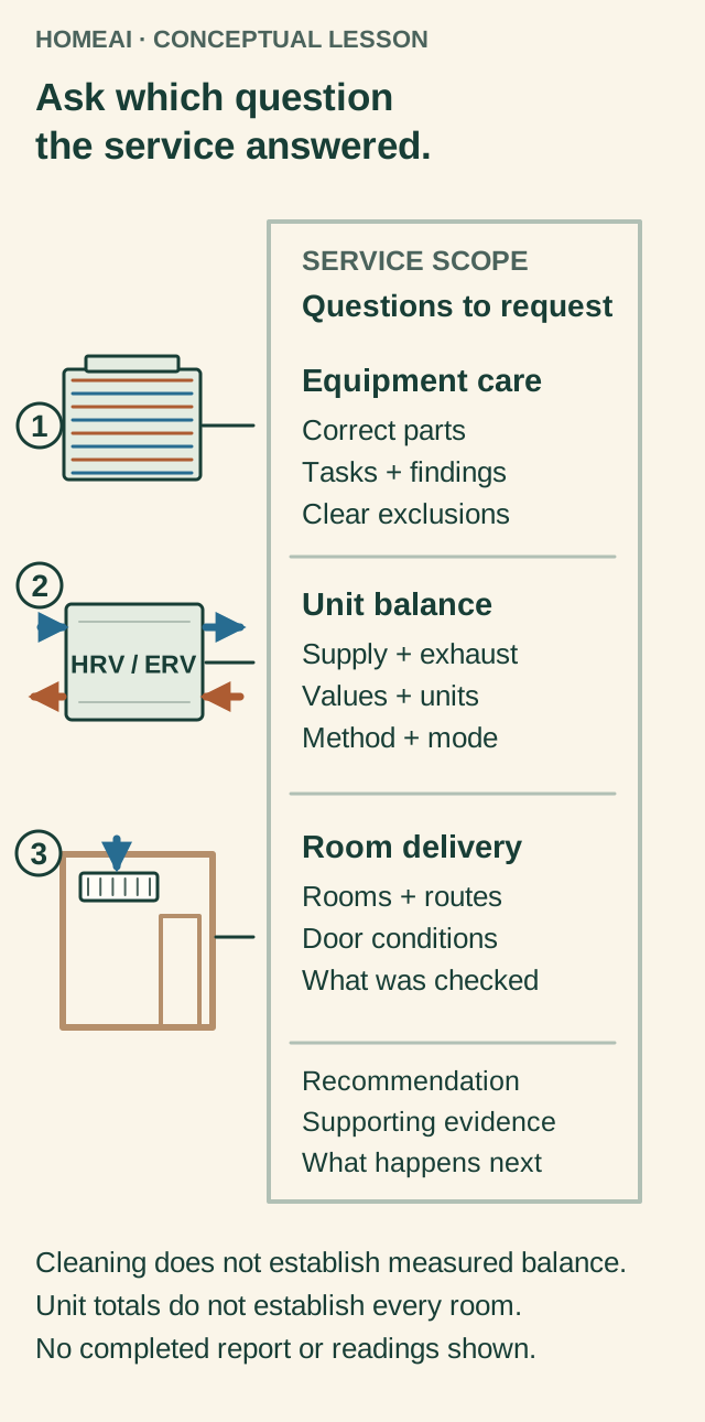
For equipment care, the record should identify the components inspected, correct filters or parts used, visible condition and any limitations. For a balance investigation, request the measured values with units, method, mode and relevant central-blower condition. For a room complaint, ask which rooms and door conditions were checked.
Controls, winter operation and drainage may need distinct checks. The service provider should distinguish a demonstrated function from one that could not be observed in that weather or operating state. If a repair or duct change is recommended, ask what evidence supports it and which follow-up measurement will show whether it addressed the complaint.
Keep unresolved items visible: an inaccessible duct route, an unidentified replacement core or an untested room is still a limit after other work succeeds. The record picture separates these scopes so the next visit can start with a precise question.
Choose the service question, then the evidence it needs
- Equipment careWhich correct components were inspected, cleaned or replaced? A care record does not by itself establish measured airflows.
- Unit balanceWhat supply and exhaust were measured, in what units and operating condition? Unit totals do not demonstrate each room’s delivery.
- Room investigationWhich rooms, door positions and distribution conditions were checked? One room or one mode does not establish all-season whole-house performance.
Use the comparison to ask what was checked, what remains unanswered and how the next step will be verified.
Sources for this comparison
Further reading: Natural Resources Canada · Keeping the Heat In, section 9.4: ventilation and combustion air; Natural Resources Canada · Heat Recovery Ventilators, revised February2012; Venmar Ventilation ULC / Broan-NuTone Canada · AI-series User and Installer Manual,1107074WEB revF; Fantech / Systemair · HERO Series Installation, Operation and Maintenance Instructions,428486-004.
Sources for this chapter
What matters when replacing equipment or handing over the home?
A replacement needs to suit the home's required ventilation and the resistance of the actual duct routes, as well as the moisture and winter conditions. Product ratings describe performance under stated test conditions. A large advertised airflow or recovery figure alone does not establish installed capacity, room delivery, operating cost or suitability for a particular home.
Ask what can remain and what needs checking: outdoor openings, ducts, insulation, distribution, controls, drainage and interaction with other equipment. A replacement cabinet is not automatically compatible with every old connection or control. Local requirements, the applicable edition and the manufacturer's instructions need to be checked for that installation rather than inferred from a general Canadian guide.
During handover, show the next occupant the identified main control, boost controls, accessible labels and normal operating instructions. Pass along the matching manuals, installed arrangement, commissioning results and service history. Explain any unresolved issue in ordinary language. Do not present an illustration, an old invoice or a running fan as proof of current performance.
If the system is shared or managed by a condominium or rental building, confirm who operates it and authorizes changes. For an individually served home, the most useful endpoint is knowing the two air journeys, the parts that support them and the person who can verify a particular concern. That understanding makes the next maintenance or comfort decision much more specific.
Sources for this chapter
Keep learning about the connected parts
- Why one room won’t warm up
- Bathroom fan not clearing moisture? Understand the whole exhaust route
- Window condensation explained: why glass gets wet and what to do next
- Indoor air sensors: know what each reading leaves out
- Carbon monoxide and gas: what to do, and how prevention works
- Suite ventilation concerns: build a useful investigation with your manager
- Living through renovation: understand work zones, air routes and handover
Canadian context and authorities · Visual atlas · Learning labs
Know the parts.
Know what the words mean.
- Heat recovery ventilator
- Ventilation equipment that exchanges outdoor and indoor air while recovering heat between the intended streams.
- Energy recovery ventilator
- Recovery ventilation equipment whose core transfers some moisture as well as heat between its air streams.
- Recovery core
- The internal assembly where heat, and for an ERV some moisture, transfers between neighbouring air passages.
- Supply air
- Air delivered toward an occupied space; its outdoor-air content depends on the identified route and arrangement.
- Exhaust air
- Air carried from indoors toward its intended outdoor discharge.
- Dedicated ventilation ducts
- Ducts serving the ventilation routes separately from central heating-air distribution.
- Integrated ventilation distribution
- An arrangement using central forced-air ductwork for some ventilation delivery or collection.
- Balancing
- Checking and adjusting the specified relationship between supply and exhaust airflows in a defined operating condition.
- Commissioning
- Verifying the installed equipment, controls and measured performance against the applicable design and instructions.
- Dehumidistat
- A humidity-responsive control that can request ventilation when its measured humidity exceeds the selected threshold.
- Recirculation
- A supported mode moving indoor air without the same exchange with outdoors as ventilation mode.
- Defrost
- A model-specific process that manages frost accumulation in cold operating conditions.
- Condensate
- Liquid water formed when water vapour cools onto a sufficiently cold surface.
- Transfer route
- The path allowing air to move between an occupied room and the rest of the air-distribution system.
- Local exhaust
- Ventilation that captures air near a source, such as a suitable bathroom or cooking exhaust system.
- Sensible heat
- Heat associated with changing temperature, considered separately from energy transfer involving moisture.
- Manual applicability
- Confirmation that the model, revision and component instructions actually match the equipment being discussed.
- Component-specific task
- Work recorded for a named part, such as a filter replacement; it does not describe every other part’s condition.
- Planned reminder
- A calendar date to review a task, separate from evidence that the task was completed.
- Maintenance history
- The dated work, findings, parts and exclusions kept for the equipment, alongside separate performance and commissioning records.
- Access limitation
- A part or task left unchecked because it could not be safely reached or was outside the agreed work.
Questions to bring
to the conversation.
- Which of the four labelled connections comes from outdoors, goes to the house, comes from the house and goes outdoors?
- Does this system have dedicated room ducts or share the central air system, and when must its blower run?
- Does the complaint affect the whole home or a particular room and door condition?
- Do the manual revision, core, filters and controls match the installed equipment?
- Will the proposed service include measured unit balance, room delivery, equipment care or a clearly stated combination?
Separate a showing observation, an existing record and a new professional assessment. Unknown means a question remains; it does not automatically mean a defect.
Use the evidence planner ↗Go to the source.
Original HomeAI explanation informed by these public references. Sources support the underlying guidance; they have not reviewed or endorsed HomeAI. Diagrams are conceptual, and calculator outputs depend on your inputs.
References read for this guide on October 24, 2026. The NRCan booklet is a February 2012 edition. The linked equipment manuals are named examples; maintenance instructions must match the installed model, revision and component.
Canadian ventilation education is read alongside current named-model manuals. Diagrams explain intended mechanisms; actual controls, care permissions, required airflow and installation requirements depend on the identified equipment and home.
Publication & source review
First published .
Sources reviewed .
- Natural Resources Canada · Keeping the Heat In, section 9.4: ventilation and combustion air
- Natural Resources Canada · Heat Recovery Ventilators, revised February2012
- Health Canada · Ventilation and the indoor environment
- Venmar Ventilation ULC / Broan-NuTone Canada · AI-series User and Installer Manual,1107074WEB revF
- Fantech / Systemair · HERO Series Installation, Operation and Maintenance Instructions,428486-004
- Health Canada · Carbon monoxide: preventing exposure
Have a question about your home?
Start with the symptom, timing and what you have observed.
Ask HomeAI